Quiet Electronics Moderated Newsgroup For The Electronic Professionals and Other Professionals > Delaware
> How to build a quick-change gearbox for your lathe
How to build a quick-change gearbox for your lathe
bounce, yer money order will get lost in the mail and yer dog won't come home.
click on our "Contact Us" icon above for the quickest response to your questions.
HOW TO BUILD A QUICK-CHANGE GEARBOX FOR YOUR LATHE
HOW TO BUILD A QUICK-CHANGE GEARBOX FOR YOUR LATHE
HOW TO BUILD A QUICK-CHANGE GEARBOX FOR YOUR LATHE
HOW TO BUILD A QUICK-CHANGE GEARBOX FOR YOUR LATHE
HOW TO BUILD A QUICK-CHANGE GEARBOX FOR YOUR LATHE
HOW TO BUILD A QUICK-CHANGE GEARBOX FOR YOUR LATHE
HOW TO BUILD A QUICK-CHANGE GEARBOX FOR YOUR LATHE
HOW TO BUILD A QUICK-CHANGE GEARBOX FOR YOUR LATHE
HOW TO BUILD A QUICK-CHANGE GEARBOX FOR YOUR LATHE
HOW TO BUILD A QUICK-CHANGE GEARBOX FOR YOUR LATHE
Build A Gearbox For Your Lathe
If you're a model engineer or a machinist then the magazine Projects In Metal is familiar to you. If not it should be. Projects In Metal is a spinoff of The Home Shop Machinist, the authority on machining and the like.
This Featured Project from "Metalworking Three" is just one of the 59 articles you'll get with the book from the magazine "Projects in Metal". Published in 1992 and 1993, more and more fine authors and machinists were jumping onto the "Projects in Metal" bandwagon. Without a lack of articles on machining, "Projects in Metal" was launched in January 1988 and was met with immediate success.
My interest in metal cutting lathes goes back a long time. I finally bought a new Atlas 6" lathe in 1979. I retired in '82, and obtained a used Atlas bench mill by 1983. The assortment of tolling with the mill included a dividinghead. With the dividing head and a single pointed tool, a new and larger pinion gear was made to repair the carriage hand drive of the lathe. I also made a few clock gears and eventually some 32 diametrical pitch gears for a two-cylinder engine.
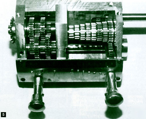
When turning a piece in the lathe, threading is often the next step and the question of cutting the thread with a die or going through the messy and tedious procedure of installing the manual change gears always surfaces. Then, once I'd cut the threads in the lathe, returning the gear train back to cutting feeds was necessary. With this sort of gear cutting experience, it became apparent that I might cut the gears myself and have the convenience of a quick change gearbox.
Let me show you how I made it.
You're going to find entirely new articles published nowhere else but Projects in Metal. You haven't seen the projects, but you probably know the names. Harold Mason, Philip Duclos, Robert Hedin, Guy Lautard, Bill Davidson, Bob Washburn, Ed Dubosky, Dick Torgerson, Steve Acker, and Deene Johnson just to name a few.
Here each author introduces their helpful and fun projects.
How to Build a Lever Operated Tailstock
Doing machine work on a small lathe requires you to develop a "feel," a close touch with it. It responds detectably to each new move you make on it. I will admit that one thing I found difficult was to judge the responses of my small lathe while attempting drilling from the tailstock.
First, let me say that I find the interrupted drilling pattern and technique caused by the small diameter feed wheel, and the difficulty in judging the machine responses to unsure feed drilling rates, totally unsatisfactory.
The result was the lever feed system I'm going to show you in the article. Let me say that it has served me well for many years.
Since I built this auxiliary for my lathe, I have never broken a center drill. There is a very sensitive response readily felt in your fingertips to all sorts of drilling conditions. Included in the photos and drawings are a number of tailstock ram attachments I have made to use with the lever operated tailstock.
How to Build A Quick Acting Tailstock Lock
Several thousand lathes out there must be employing a through bolt with nut and captive wrench to lock the tailstock.
While effective, this is an awkward, time consuming method and, after much use, can lead to injury when the wrench slips, Finally, since many jobs require frequent locking and unlocking of the tailstock, it can be quite frustrating as well.
Of course, some lathes have quick acting locks, but they usually cost much more. Years of my dreaming about possible conversion schemes finally led to the present answer which was surprisingly easy and effective.
A Lever Operated Tailstock Clamp
Owners of 12" Atlas/Sears lathes will find this lever operated tailstock clamp an improvement over the original captive wrench. The limited angle of wrench travel usually requires repositioning it to provide enough turns to tighten adequately and release.
The modifications to the tailstock are minimal and do not prevent reverting back to the original wrench and bolt clamping method if for any reason the project is not completed.
All of the machining can be done with a lathe and a small mill. Since there's only minimal machines needed to do this, there's no excuse for you not getting on it!
How to Make A Set of Boring Bars
Anyone who has just acquired his first lathe will do well to begin with a good set of boring bars. Boring is just as much a part of lathe work as turning. I mention this because I remember my first attempt at boring a hole. The tool as the type sometimes seen in old lathe makers' catalogs, on one of the back pages, as though offered as an afterthought. It had a thin thank with a crook at the end like a sheep hook. Naturally the results were what anyone wiser that I was at the time would expect; the tool chattered and had to be urged through the hole several times just to remove a tiny bit of metal, Such a flimsy tool lacked rigidity, and needed a gaping hole to start with just to swallow it, besides. If, at this sage, I have steered anyone away from using such a tool I have already accomplished something.
Eventually, I acquired some proper boring bars - the type that mount round or square tool bits at either end. At one end, the bit is mounted at a 90 degree angle to the shank, and at the other end at a 45 degree angle, allowing it to project in advance of the shank for boring blind holes. Those turned out to be perfectly satisfactory tools, and eventually all that was required was a greater range of sizes.
It is commonly known that the rigidity of a bar of a given material and given length increases far more than in direct proportion to any given increase in diameter.
To supply the missing boring bars, my first thought was to get out the tool catalogs again; but that gave way to the idea of making them, and then to the idea, while the tools were out and scattered around anyway, of making an entire set, replacing the ones already on hand that where looking rather scruffy. The project turned out to be little more than an evening's work. It would be an exercise well suited for trying out the new lathe- and maybe a little bit of one's ingenuity.
Are you guys up to the challenge?
How to Make Two DROs (digital readouts)
Let me tell you how I came to develop a digital readout (DRO) for my milling machine for about $100 per axis and how you, too, can build one, cased on the technology used in digital calipers.
The DRO has 0.0005" resolution and approximately 0.002" accuracy. I have also included some information about a quadrature encoder counter with built-in LCD display.
This can be used with an inexpensive rotary encoder to build a 0.001" resolution electronic travel dial or as the counter/display for a conventional linear encoder spar.
Plus 23 more projects involving techniques and making lathe accessories.
Conversion to three phase power
Expanding your arbor press capability
Holding thin material for machining
Drilling accurately centered cross holes in round stock
Machining internal threads - a different approach
On the subject of stiffness and overhang
The rise and fall of the Taiwanese bandsaw
Truing the column of a mill-drill machine
A low cost adjustable counterbore
An easy way to make a multi-position tool post
A lever tailstock feed for the center lathe
Reversible lathe carriage stop
Spindle mounted collet attachment for your lathe
Make a Drill Sharpening Fixture and
An accurately sharpened drill is needed to make an accurate hole. When the point of the drill is split, less force is required to drill the hole. Using a sharpening fixture with a point splitting grinder will make the best drill point.
The fixture I'm proposing sharpens with flat facets rather than the common curved relief point - a primary relief of 8 to 10 degrees on the cutting edge of the drill lips and a secondary clearance of about 18 degrees. Also, the included angle of the point is 140 degrees, which is built into the fixture.
This point angle makes a shorter chip, and so requires less power when drilling. After the drill is sharpened, a dull chisel point connects the cutting edges. This point neither centers the drill nor cuts. The point splitting grinder changes the chisel point into a cutting tool.
How to Make an Index Plate for a 4-3/4" Center Height Dividing Head
In a small village fairly close to my home I recently discovered an "Aladdin's Cave" second hand tool shop. It has all the tools one dreams about from metalworking lathes to old-fashoined wood molding planes. Here one can spend a happy hour going through drawers full of tools of all descriptions.
During my last visit I found tucked away in a corner an old, heavy, and fairly rusty dividing head. There was only one index plate, and missing were the set if differential indexing gears, the gear quadrant, and the tailstock.
After a good thorough inspection, I decided it was too good an opportunity to miss for the price asked, as I could make the missing parts in my home workshop.
I was the second indexing plate with the second group of hole circles and I will show you how I i produced the second index plate.
Since The Home Shop Machinist first went into publication, we have seen several good articles and idea on the subject of resharpening end mill cutters. The ideas presented have all been good ones and the purpose of the idea presented here is not to find fault but rather suggest a slightly different approach to the problem. A better approach? I believe it is.
With this fixture it is possible to take cutters spoiled by that nerd who thinks he can regrind end mills by hand - as well as those broken or burned - grind them down flat to where radial cutting is good, then regrind the primary and secondary angles and resharpen.
This fixture is different in that the main body is machined to use the collets that fit your milling machine so it fits any size shank you have collets for. So with that out of the way, get this article and get to work.
I have scrounged around for several years looking for a good metal cutting band saw, but there was always something wrong with the price, looks, or condition. It didn't need to be a large one, but it had to have low speeds and high speeds. A 100 to 1,000 fpm would be fine.
It seemed like everyone kept their band saws for posterity. Being a retired machine designer, I decided to design and build one with materials I had on hand or that could be easily obtained.
I'm going to show you how I did it.
How to Build a Dedicated Tapper
For the average home worker, the biggest turnoff in any project is likely to be the need for castings. Apart from the cost, there may not be a foundry within reach or suppliers may not be doing the castings you want. Relax!
This dedicated tapping center project does not use castings. So if that's what's bothering you, I've just taken away your excuse. Let's get to work.
Build An Internal/External Center Finder
I had a job that required setting up a machined piece in the milling machine. The part already had a bored hole and required that it be centered to make cuts on its rim. I know there is an attachment commercially available, but I can't justify or afford the approximate $200 cost.
I have seen the attachment in the catalogs but have not seen the actual part. I don't know if this is similar, but in any case it is not a copy. The following is my solution. I just completed it so it hasn't been in use for very long, but it seems to work very well. Using the dials on the horizontal feed screws, I could get a repeatability within plus or minus .001".
Make a Precision Metal Stamper
I've occasionally had to stamp figured in a pattern by holding the steel stamp with one hand and banging it with a hammer with the other. In doing so, I always held it as best I could to vertical position and location orientation.
In addition, I tried to deliver the correct amount of force to make the impression depth uniform with other figures, regardless of whether a figure 1 or 8 was being stamped. As best I could!
A vertical mill has all the coordinates and accessories necessary to align the spindle for stamping items of any geometry. Why not make a sort of special automatic punch with a business end that will receive the metal stamps instead of the standard point, then insert it into the mill spindle? The method of changing the stamps can be quick and easy and the device can be very small. The down pressure of the quill, actuated by the handle on the side, will provide the necessary force. The actual force at the stamping end will be adjustable as with any standard automatic punch.
Mill vise: rework for precision
Instant soft jaws for the vise
Economy substitute for a bridgeport
Getting rid of chips on your band saw
Rules - differential and difference
A very handy one inch height gauge
From shears to brake: a boxing story
Any one of these projects is worth the small cost of the book! If you're just learning about machining or you're an old pro this book has the information you need and it belongs in your head. Now's your chance to get ahead - don't miss it!
8-1/2 X 11" Hardcover, 261 pages, profusely illustrated with photographs and working drawings.
Visit my MarketplaceAdvisor Gallery! Power Tools for Power Sellers!
Phone: (***) 744-4449 M-F 9:00 to 4:00 Pacific Standard Time
This item has been seen by alt people!