Quiet Electronics Moderated Newsgroup For The Electronic Professionals and Other Professionals > Kentucky
> Used
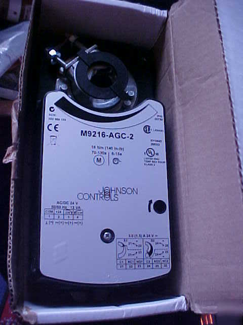
> M9216 -agc-2 electric spring return actuator vac/vdc
M9216 -agc-2 electric spring return actuator vac/vdc
M9216-AGC-2 Electric Spring Return Actuator
Johnson Controls M9216-AGA-2 Electric Mtr Actuator 140 IN-LB 70-130 S 24 VAC/VDC 50/60Hz Sprg Rtn Incr. Floating
M9216 actuators are designed to position air dampers and valves in Heating, Ventilating, and Air Conditioning (HVAC) systems. Applications include: • positioning return air, exhaust, or outdoor air dampers • controlling face and bypass dampers • positioning blades for variable volume fans positioning VG1000 Series ball valves and
VG7000 Series globe valves when used with an M9000-5xx Valve Linkage. Refer to the manufacturer’s information to properly size the damper, valve, and/or actuator
M9216 actuators operate on 24 VAC at 50/60 Hz or 24 VDC. They use a DC motor with stall detection circuitry that operates throughout the entire stroke. The proportional and resistive actuators employ noise-filtering techniques on the control signal to eliminate repositioning due to line noise. Mounting two each M9216 (BGx, GGx or HGx) models in tandem provides twice the amount of running torque as a single unit. Rotation is mechanically limited to 93° by integral end-stops. The position of the actuator is visually indicated from 0 to 90° on the cover. An anti-rotation bracket prevents lateral movement of the actuator. The damper position may be set manually with the manual override feature in the event of a power failure.
M9216 Series Electric Spring Return Actuators
AGx, HGx, JGx: 20 to 30 VAC at 50/60 Hz or 24 VDC ±10%, 12 VA supply, Class 2
BGx: 20 to 30 VAC at 50/60 Hz or 24 VDC ±10%, 10 VA supply, Class 2
GGx: 20 to 30 VAC at 50/60 Hz or 24 VDC ±10%, 14 VA supply from 32 to 122°F
(0 to 50°C) or 18 VA supply from -22 to 32°F (-30 to 0°C), Class 2
AGx: 24 VAC at 50/60 Hz or 24 VDC, 4.8 mA (on/off mode, 500 mA maximum)
BGx: 24 VAC at 50/60 Hz or 24 VDC, 420 mA maximum
GGx, HGx: 0 to 10 VDC or 0 to 20 mA
JGx: Potentiometer value is 100 ohms minimum to 10,000 ohms maximum
AGx Factory Setting: Terminals 1 and 3, Clockwise (CW) rotation; Terminals 1 and 4,
Counterclockwise (CCW) rotation
BGx Factory Setting: Terminals 1 and 2, CW rotation
GGx (Voltage or Current Input):
Switch Selectable: 0 (2) to 10 VDC or 0 (4) to 20 mA
Factory Setting: 0 to 10 VDC, CW rotation with signal increase
HGx (Voltage Input or Current Input):
Jumper Selectable, Fixed: 0 (2) to 10 VDC or 0 (4) to 20 mA
Adjustable: Zero, 0 to 6 V (0 to 12 mA); Span, 2 to 10 V (4 to 20 mA)
Factory Setting: 0 to 10 VDC, 0 to 20 mA, CW rotation with signal increase
GGx, HGx, JGx: Direction of action is user selectable Direct (CW) or Reverse (CCW)
GGx, HGx: Voltage Input, 200,000 ohms; Current Input, 500 ohms
GGx, HGx: 0 to 10 VDC or 2 to 10 VDC for 90° (10 VDC at 1 mA)
Corresponds to input signal span selection and rotation limits.
JGx: 0 to 10 VDC for 90° (10 VDC at 1 mA)
xGC: Two SPDT (Single-Pole, Double-Throw) switches rated at 24 VAC,
1.5 A inductive, 3.0 A resistive, 35 VA maximum per switch, Class 2
Factory Setting: CCW; Direction is selectable with the coupler.
All Models: 140 lb·in (16 N·m) for one unit
BGx, GGx, HGx: 280 lb·in (32 N·m) for two units in tandem
Adjustable from 30 to 90°, CW or CCW, mechanically limited to 93°
70 to 130 seconds for 0 to 140 lb·in (0 to 16 N·m); 90 seconds nominal at 50% rated load
(Powered rotation is faster in the spring return direction than in the spring winding direction;
power failed spring return is less than 15 seconds.)
GGx: 1/4 in. spade terminals with pluggable terminal blocks (See Table 2.)
All Other Models: Screw terminals for 22-14 AWG; maximum of two 18, 20, or 22 AWG each
M9000-100: One included with all models; two included with AGD, AGE, and xGC
3/8 to 3/4 in. (10 to 20 mm) diameter round shaft; 3/8 to 5/8 in. (10 to 16 mm) square shaft
Operating, GGx: -22 to 122°F (-30 to 50°C); 0 to 95% RH, non-condensing
All Other Models: -4 to 122°F (-20 to 50°C); 0 to 95% RH, non-condensing
Storage, All Models: -40 to 186°F (-40 to 86°C); 0 to 95% RH, non-condensing
9.82 x 4.57 x 3.62 in. (249.4 x 116.0 x 91.9 mm)
UL 873 Listed, File E27734, CCN XAPX
CSA C22.2 No. 139 Certified, File LR85083, Class 3221 02
CE Mark, EMC Directive 89/336/EEC
The performance specifications are nominal and conform to acceptable industry standards. For application at conditions beyond these
specifications, consult the local Johnson Controls office. Johnson Controls, Inc. shall not be liable for damages resulting from misapplication